Posted: April 3rd, 2014 | Author: sabre1041 | Filed under: Technology | Tags: Camel, OpenShift, SwitchYard | 2 Comments »
 In an earlier post, I introduced a custom Apache Camel component that can be used to manage the OpenShift platform. It allows for the invocation of operations that control key components of the OpenShift lifecycle such as displaying user metrics and managing applications. The operations and metrics generated from this component can be used in a variety of applications that leverage the Camel framework to solve business goals. Camel can be deployed to a variety of runtime environments ranging from servlet containers such as Tomcat, application servers such as JBoss , OSGi containers such as Karaf, or even self sufficient as a standalone application. To demonstrate the functionality of the OpenShift Camel component in a project, we will leverage SwitchYard and JBoss as the running environment within a sample project called camel-openshift-switchyard. SwitchYard is a services delivery framework for running and managing service-oriented applications. By running on SwitchYard, it will allow for the opportunity to cover both the OpenShift Camel component and developing and running applications using Switchyard. This post will provide an overview to the sample project including the steps necessary to configure and deploy either in your own environment or on the OpenShift platform. In subsequent posts, we will review the project in depth including how Camel can be integrated into a SwitchYard project and how to integrate the OpenShift Camel component in a project of your own.
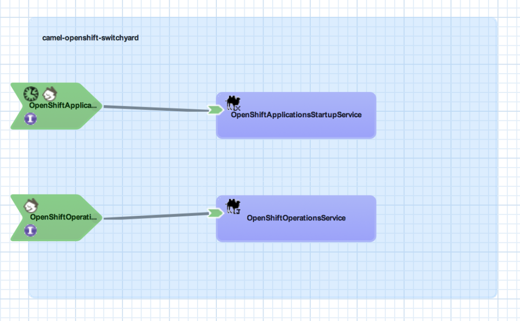
The camel-openshift-switchyard project consists of a SwitchYard application and a basic web application that can be used to invoke services exposed by SwitchYard. The SwitchYard application contains two services: OpenShiftOperationsService and OpenShiftApplicationsStartupService. Each contains Camel routes utilizing the OpenShift Camel Component. The OpenShiftOperationsService invokes operations against a given users’ account such as retrieving the details of a given domain or applications within a domain. Meanwhile, the OpenShiftApplicationStartupService will attempt to start any Application associated to a user that is not currently started. A diagram depicting these services and the overall SwitchYard composite is shown below:
Both services contain a RestEasy binding to allow for external invocation via REST. The OpenShiftApplicationsStatup service also contains a timer binding which will initiate the service at the top of each hour based on a cron schedule. To take advantage of the scheduled service operation, the following two system properties must be configured either within the application itself or on application platform.
- openshift.user – The login of the OpenShift user
- openshift.password – The password on the account
Testing
Included in the project are a series of integration tests designed to validate the functionality of the application and to demonstrate the testing capabilities of SwitchYard applications. Injection of property values and invocation of Services and HTTP resources are some of the components demonstrated.
Building and Deploying
The project is hosted on GitHub and can be cloned into a local environment by running the following command:
git clone https://github.com/sabre1041/camel-openshift-switchyard.git
Prior to built or imported into an IDE, certain project dependencies must be configured. A core project dependency is the OpenShift Camel component which must be installed and available in the local Maven repository. Because this library is not part of any publicly available repository, initialization scripts for both Windows and Unix have been provided to configure the required dependencies. This script is found in the support folder of the project. Execute the init.sh or init.bat depending on your Operating System.
Next, build the project using Maven by running the following command:
mvn clean install
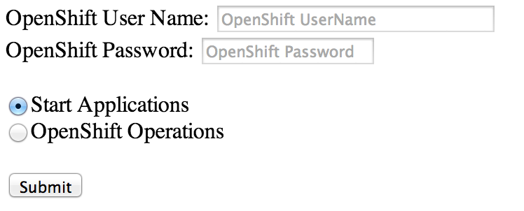
With the project now built, deploy the archive to Fuse Service Works or a JBoss container with SwitchYard installed. Once deployed, the application can be accessed by browsing to http://localhost:8080/camel-openshift-switchyard/
Deployment to OpenShift
The project has been configured to be seamlessly deployed to the OpenShift Platform. OpenShift provides the functionality to utilize custom cartridges which are not part of the core OpenShift platform to host applications. Since this project is built on SwitchYard, we will leverage a custom JBoss EAP 6 cartridge preconfigured with the SwitchYard runtime. The OpenShift Web interface provides the ability to specify a custom cartridge and existing source code during new application creation. However, due to the number of dependencies required by the SwitchYard platform, the project is unable to be built and deployed prior to the default application creation timeout. To get around this limitation, we will create the application using the OpenShift command line tools (RHC), merge the local OpenShift project with the camel-openshift-switchyard project hosted on GitHub, then finally push the application to OpenShift. Using the terminal in the location where the repository of the newly created application will be created on your local machine, issue the following command to create an application using the custom SwitchYard cartridge as the container.
rhc app create <app-name> "http://cartridge-switchyard.rhcloud.com/manifest/466c7020661420c4604e870802fe673244861a5a"
After the application was successfully created and the source code now available on your machine, change into the application directory:
cd <app-name>
First, add the GitHub hosted project as an upstream Git remote repository
git remote add upstream -m master https://github.com/sabre1041/camel-openshift-switchyard.git
Next, pull in the changes from the upstream repository
git pull -s recursive -X theirs upstream master
Finally push the changes to OpenShift
git push origin master
OpenShift will then handle obtaining the required dependencies, building and deploying the project. Once complete, the application can be viewed in a web browser. To determine the URL of an OpenShift application from the command line, execute the following command:
rhc app show <app-name>
You should be able to browse to the URL and utilize the application as you would on your local machine.
As mentioned previously, we will walk through the project in detail in a future post. This will allow for the demonstration of SwitchYard components and provide examples of how the OpenShift Camel component can be used in projects of your own.
Posted: February 23rd, 2014 | Author: sabre1041 | Filed under: Technology | Tags: OpenShift, VirutalBox | No Comments »
In the past, I have demonstrated several projects and features for OpenShift, Red Hat’s Platform as a Service product. You may be aware of OpenShift Online, available at http://openshift.com, for seamless deployment of applications to the cloud. What you may not be aware is that OpenShift Online is only one of the OpenShift products available. The OpenShift line of products features 3 solutions: Online, Origin and Enterprise. While OpenShift Online may suit your public cloud needs, there may be interest in establishing a private or hybrid cloud solution within your enterprise. The best way to become familiar with a product is to install and configure it yourself on a local machine, such as a personal desktop or laptop. Evaluating cloud-based technologies on a single machine typically requires the use of virtual machines to replicate multiple machines or environments. However, applying the appropriate configurations when leveraging multiple virtual machines can be challenging as they must be able to communicate both with each other as well as the external Internet. In the following discussion, we will walk through the process of configuring the supporting infrastructure of a minimal installation of a private OpenShift environment using Oracle VirtualBox.
While there are several virtualization products on the market today, we will utilize Oracle VirtualBox primarily due to its ease of use and compatibility with multiple platforms. Before we begin the configuration process, let’s discuss what an OpenShift environment consists of. A typical basic installation of OpenShift requires the allocation of two machines: A Broker, which handles user and application management, and a Node which provides hosting of cartridges and the actual storage of applications deployed by users, which are contained within gears. Communication between broker and node instances is critical to the performance of the OpenShift environment and presents the greatest challenge when configuring the virtual instances. We need to provide an environment that fulfills the following requirements:
- Host can communicate with each virtual guest
- Virtual guests can communicate with each other
- Virtual guests can access external resources on the Internet
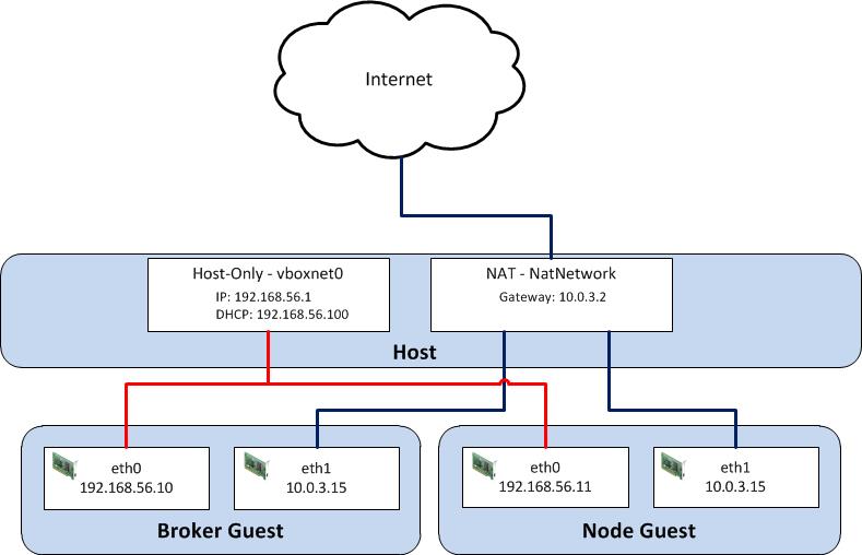
VirtualBox, similar to most virtualization software, supports several network hardware devices that can be run in a variety of networking modes. A full discussion of the different types of network devices and modes VirtualBox can be configured in can be found on the VirtualBox website . To accommodate the aforementioned requirements, we will leverage multiple network adapters running in separate networking modes. The first adapter will be configured in host-only mode as it creates a private network among each virtual machine configured with this network type and the host. The limitation when running in host-only mode is there is no access to external resources such as the Internet. To allow access to external networks within each guest, a second adapter is configured in NAT networking mode. NAT networking is one of the modes VirtualBox provides for allowing a guest to connect to external resources. It was chosen as it requires the least amount of work and configuration by the end user and is ideal for simple access to external systems. An overall diagram of the virtual machine network architecture can be found below.
Posted: February 10th, 2014 | Author: sabre1041 | Filed under: Technology | Tags: Camel, OpenShift | 3 Comments »
Since its creation in 2007, the Apache Camel project has allowed developers to integrate systems by creating Service Oriented Architecture (SOA) applications using industry standard Enterprise Integration Patterns (EIP). At its core, Camel is a routing engine builder for which messages can be received and processed. The processing of messages uses a standardized API library backed by an extensive collection of components which abstracts the actual implementation of routing and transformation of messages. These components also include the ability to communicate with external systems through an array of protocols ranging from web services, REST and JMS. With more than 80 components in the standard Camel distribution, developers have the flexibility to perform power operations with minimal effort to suit their business needs. One of the benefits of the Camel component framework is that it was designed as a factory system where new components can be easily added to solve a business use case.
As more companies and individuals look to migrate their operations and applications into cloud-based solutions, the management of these resources can prove to be a challenge. The overall architecture may be different than what many individuals are accustomed. The OpenShift Platform as a Service (PaaS) is one such cloud offering where developers can quickly create powerful scaled applications without having to worry about managing infrastructure or complex software installation.
Introducing the OpenShift Camel Component
Imagine being able to communicate with the OpenShift Platform directly through a Camel route? With the OpenShift Camel component, it is now possible. Exposed through an Endpoint as both a Camel Consumer and Producer, OpenShift resource details can be retrieved or modified all within a Camel route. Want to find out information about a particular OpenShift Domain, such as the applications and their details? How about automating application deployments? These are only some of the possibilities now available.
Communication between the OpenShift Camel component and OpenShift is facilitated by using the REST API exposed by the OpenShift platform and the OpenShift Java Client. Responses from the OpenShift Camel component will be returned using the API from the OpenShift Java Client.
Using the OpenShift Camel Component in your project
The OpenShift Camel Component can be easily added to a new or existing project. The following steps will describe how this can be accomplished.
GitHub Project: https://github.com/sabre1041/camel-openshift
- Fork/Clone the GitHub repository
git clone https://github.com/sabre1041/camel-openshift.git
- Build the project using Maven
mvn clean install
- Add the component to a new or existing Camel Project as a Maven dependency in the projects’ POM file.
<dependency>
    <groupId>org.apache.camel</groupId>
    <artifactId>camel-openshift</artifactId>
    <version>0.0.1-SNAPSHOT</version>
</dependency>
- The following example implementation will retrieve information about the authenticated user and print out their user details to the log:Java DSL
import org.apache.camel.builder.RouteBuilder;

public class PrintOpenShiftUserRoute extends RouteBuilder {

    public void configure() throws Exception {
        // Retrieve User Details
        from("openshift://user?userName=<openshift_username>&password=<openshift_password>")
            //Print to Log
            .log("${body}");
    }

}
Spring XML
<route>
<description>Spring XML Route. Full XML omitted for brevity</description>
<from uri="openshift://user?userName=<openshift_user>&password=<openshift_password>"/>
<log message="${body}"/>
</route>
With the steps above complete, the project can be deployed to a running container or unit tests can be created to verify the expected results. Additional functionality including how to leverage Authentication as Message Headers can be found on the GitHub project page.
In an upcoming post, I will demonstrate several uses for the OpenShift Camel including how the component can be leveraged within a SwitchYard application.
Posted: November 16th, 2013 | Author: sabre1041 | Filed under: Technology | Tags: OpenShift | No Comments »
 Deploying an application to the OpenShift Platform as a Service (PaaS) can be accomplished in only a matter of minutes due to the wide array of tools available to the developer. One of the tools provided by OpenShift is the ability to add the Jenkins Continuous Integration server to the development lifecycle of an application. The inclusion of Jenkins affords several incentives for both developers and stakeholders of any development project. First, by adding Jenkins to an OpenShift application, the build process is delegated to Jenkins resulting in far less downtime for the application as typically the application is taken offline during the build and deployment process. Secondly, it brings in the Jenkins Continuous Integration server, with its wide array of plugins and large community support, into your environment. Jenkins is one of the components that make up a continuous integration environment which is a set of software tools responsible for the assembly and distribution of software artifacts. The primary components of this environment consist of a build process, version control system, continuous integration server and finally a repository manager. The OpenShift ecosystem contains the majority of the components with an exception of not being able to easily access and store artifacts that have been assembled as a result of a build process. This process is typically delegated to the final component of the continuous integration environment: the repository manager. One of the more popular repository managers available on the market today is Sonatype Nexus. Nexus can serve multiple purposes in an environment as it can be a central location for binary artifacts and their dependencies, act as a proxy between your organization and publically available repositories, and serve as a deployment destination for internally created artifacts.
Each component of an OpenShift application, whether it is a web or database server framework, is known as a cartridge and there are wide number of cartridges readily available today. One of the benefits of the OpenShift cartridge system is the ability to leverage downloadable user cartridges to extend the base set of included cartridges. By offering Nexus as a downloadable cartridge, it would allow for the completion of creating a continuous integration environment in the cloud. To learn more about a continuous integration environment and how to build one of your own, refer to the following link: http://www.redhat.com/resourcelibrary/whitepapers/eap-create-compile-and-deployment-environment
The Nexus cartridge project is hosted both on GitHub and on OpenShft and built using the Cartridge Development Kit. By leveraging the CDK, an end user can choose the particular build of a cartridge to add to their application. The Nexus cartridge project is available at the following locations:
After selecting the CDK link above, you can use the OpenShift RHC Client tools or the web console to add the cartridge to an application based on the information provided. If you are using the client tools, you can use the command presented at the top of the page which represents the most recent build from the master branch of the project to create an application. When using the web console, first login and click Add Application. Downloadable cartridges can be added by entering the location of the cartridge manifest in the textbox provided in the “Code Anything” section. Click Next, enter the name for the newly created application using the Nexus cartridge, and click Create Application. After the cartridge has been created, you will be presented with a confirmation and the user name and password for the Nexus administrator account. After waiting a few moments to allow the server to come online, you can click the application link provided which will bring you to the Nexus server start page. More information on how to configure and utilize Nexus can be found at the following documentation page: http://books.sonatype.com/nexus-book/reference/
At this point, you have a fully functional repository manager hosted in the cloud. In an upcoming post, I will demonstrate how you can create a fully functional continuous integration environment hosted on the OpenShift platform.
Posted: October 28th, 2013 | Author: sabre1041 | Filed under: Technology | Tags: Java, JBoss | 1 Comment »
Separating the configuration parameters of an application from the source code is considered best practice as it allows for an application to be more versatile. Instead of being tied to a particular configuration by hardcoding values in the source code, parameters can be externally accessed and loaded according to the particular environment the application is running in. In Java, these values are typically stored in Properties files on the Java classpath or as system properties within the JVM. Java containers also provide methods and utilities for storing and loading configuration values for use by applications. The following discussion will explore the various methods for using property values on the JBoss Enterprise Application Platform version 6.1 and above.
Most Java developers are familiar with the basics of Properties files: sets of key/value pair strings stored in files with the .properties extensions. A basic example of loading a properties file within an application can be accomplished with the following code:
InputStream is = Thread.currentThread().getContextClassLoader()
     .getResourceAsStream(PROPERTIES_FILE_NAME);

Properties properties = new Properties();

try {
	properties.load(is);
} catch (IOException e) {
	LOGGER.error(e.getMessage(), e);
}
finally {
	try {
		is.close();
	}
	catch(Exception e) {

	}
}
The most common method of using a properties file is to package them within an application such as a Java archive (JAR) or web archive (WAR). Doing so will automatically place the file on the classpath for use by the application. In addition, there are several alternate methods that can be used. To demonstrate some of these methods, a sample application has been created to illustrate how this can be accomplished within an application deployed on JBoss EAP 6.1. It is hosted on GitHub at the following location:
https://github.com/sabre1041/jboss-properties
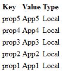
The project consists of a simple servlet which loads a specific properties file from the classpath, iterates through each of the keys, and prints out the value. In addition to using the value found from the properties file, the application will search for the existence of a system property from within the JVM and print out its corresponding value. The project can be built using Maven by navigating to the location where it is stored on your machine and executing the following from the command line:
mvn clean install
This will produce a web archive file named jboss-properties.war file inside the target folder which can be deployed to the JBoss server. For more information on how to deploy applications to JBoss, please refer to this link. After deployment and assuming the JBoss server is running on your local machine, the application can be accessed at http://localhost:8080/jboss-properties with the following presented:
Posted: October 6th, 2013 | Author: sabre1041 | Filed under: Technology | Tags: SwitchYard | 1 Comment »
Creating and deploying software in a service oriented architecture (SOA) environment can be a daunting task. Some of the challenges one can face are the complexities of communicating with external systems, transforming data between multiple formats and the management and orchestration of multiple services. There are a number of well-established frameworks available that one can choose from including IBM WebSphere ESB, ActiveMatrix from TIBCO, and Microsoft’s BizTalk server. One of the more recent implementations of a services framework is SwitchYard. While similar to a traditional Enterprise Service Bus (ESB), SwitchYard aims to provide a “lightweight service delivery framework providing full lifecycle support for developing, deploying, and managing service-oriented applications”. So what does that really mean to both developers and stakeholders? For developers, Switchyard provides integration with multiple well established frameworks including Apache Camel, Drools, and jBPM for managing long running business processes. In addition, rich testing support allows for the validation of components at each level of the development process. For stakeholders, SwitchYard provides multiple levels of governance support by interacting with the S-RAMP artifact repository for design time governance and JBoss Overlord for runtime governance. SwitchYard has gained the support and confidence from Red Hat to drive the next version of their Service Oriented Architecture Platform (SOA-P) replacing the existing Rosetta based ESB offering. Over the course of the following several posts, we will discuss how SwitchYard can be deployed within an organization using a real life business use case. In the process, we will discuss several key components within the SwitchYard toolkit. Finally, we will explore how to deploy a SwitchYard project to both a local JBoss installation and an installation deployed on Red Hat’s Openshift Platform as a Service (PaaS) offering.
To establish a business use case for a SwitchYard and to illustrate practical implementations of various SwitchYard components, we will utilize SwitchBrick; a fictitious company in the electronics recycling market who is looking to improve a key aspect of their business. SwitchBrick’s business model is similar to other competitors in their marketplace; consumers trade in their used electronics in exchange for cash. What differentiates SwitchBrick from its competitors is that instead of requiring consumers to ship their product to the company to receive compensation, consumers can visit an automated kiosk to complete the exchange process. SwitchBrick sales have been consistently improving largely due in part to the customer feedback they have received. Seeing how this feedback mechanism has been so critical to the success of the business, they are looking at ways to improve their business process and technology stack. At the present moment, consumers can submit feedback to SwitchBrick in one of two ways:
- At the conclusion of a transaction at an automated kiosk
- A form on the SwitchBrick website
While the two systems are not currently integrated, they each perform the same overall functionality. A customer enters their email address and any comments they may have. In addition, the customer is given the opportunity to subscribe to the SwitchBrick newsletter which will entitle them to exclusive offers such as bonuses on future exchanges. Once records are submitted and hit backend systems, they are validated and if the consumer chose to subscribe to the newsletter, a notification is sent to the email provided confirming their subscription. The following diagram provides a visualization of the feedback process.
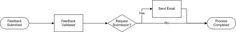
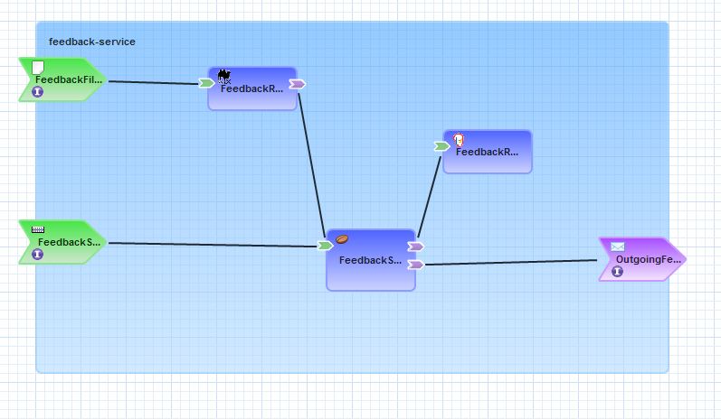
Now that we have a basic understanding of the feedback process, let’s discuss some of the specifics of their implementation as we continue to set the stage for integrating SwitchYard components. Feedback submitted at a physical kiosk and from the website are not treated the same primarily due to the process in which the records are received. Records submitted on the SwitchBrick website are received in real time via JMS while at the end of the day, each kiosk will batch up an entire day’s worth of records represented as a flat file in a CSV format. SwitchBrick already has a canonical model for their Feedback system which the website adheres to. The key is to transform the CSV records received from kiosk locations into this format before continuing on with the process. Once the records have been transformed into a canonical model format, validation and business rules can then be applied. Finally, if a subscription is requested, a notification is sent to the email submitted as part of the original request. For brevity of this example application, no persistence to a datastore will be attempted but one can assume this step exists in a real life implementation. With an end to end understanding of the feedback process, here’s how it can be visualized:
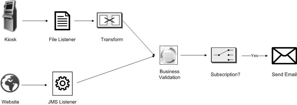
For those who have had previous experience working in a message oriented middleware (MOM) environment may recognize the icons representing the transform and subscription steps of the applications in the diagram above. Those icons signify a transformation and content based router Enterprise Integration Patterns (EIP). An EIP is based on an accepted solution for a given context when designing complex message based systems. Gregor Hohpe and Bobby Woolf’s Enterprise Integration Pattern book, which is approaching its 10 year anniversary, is still considered the go to reference when designing message based architectures such as SwitchYard. The Apache Camel project has also assembled a quick reference guide for the majority of commonly used patterns on their website. Having a basic understanding of Enterprise Integration Patterns is a key still to attain before working with SwitchYard.
A key feature of SwitchYard and the development toolkit it provides is the support for visualizing components of a SwitchYard application graphically. This visualization allows for a live representation of the state of the application instead of having to leverage third party tools such as Microsoft Visio or open source applications such as OpenOffice/LibreOffice Draw or Dia to depict the application after the fact. Since we have all the steps in place to start developing an application, here’s how it would be modeled within SwitchYard (yes, like a good TV chef, the final product has already been completed):
In the next post, we will get down to business demonstrating in detail the steps required to create to create a SwitchYard application using the SwitchBrick use case as our guide. Along the way, we will introduce commonly used SwitchYard components, illustrate how they can be used, and review how to test and validate the execution of an application. In the meantime, be sure to check out the SwitchYard product page which includes references for getting your hands on SwitchYard, product documentation, and sample projects.
Posted: July 31st, 2013 | Author: sabre1041 | Filed under: Technology | Tags: JBoss, Tips, Tricks | 2 Comments »

Yes Chris, even you can set a timeout value
There are multiple methods for configuring the JBoss Enterprise Application 6 server. These options range from using the Management web interface, the Command Line Interface (CLI) tool, or manually editing the XML configuration file (not recommended, but still available as an option). One of the benefits of using the JBoss CLI tool is that it not only allows for the management of almost every option available in the EAP server remotely (the Management console only exposes a subset), but it allows for tasks to be scripted and run in a repetitive manner. I have used the CLI tool for everything from provisioning the initial configuration of server instances, monitoring platform metrics, to performing nightly deployments as part of a continuous integration environment. One of the issues that I have frequently faced is the CLI tool would time out while connecting to the JBoss Instance. This situation tends to occur more frequently on remote instances or on instances that have their management interface secured with SSL as it takes longer for the handshake exchange process to complete.
The default timeout value for the CLI to connect to a remote JBoss instance is 5000ms (5 seconds). Users can provide their own timeout value along with a number of other configuration options in a file called jboss-cli.xml. The CLI tool will search for this file in three (3) locations:
- The current directory where CLI tool is invoked from
- Setting the location of the file in a Java Property called jboss.cli.config
- Within the bin folder of the JBoss server defined by the JBOSS_HOME environmental variable.
The JBoss server itself provides a jboss-cli.xml file in the <JBOSS_HOME>/bin folder which can be used as a starting point for any custom modifications. This file is used when invoking either the jboss-cli.bat or jboss-cli.sh script depending on the operating system platform to connect to a local or remote instance. As previously mentioned, I utilize the CLI tool to handle remote deployments of artifacts. This is a centralized server and JBoss is not installed locally on this machine. The JBoss platform provides a client jar to leverage access to the CLI named jboss-cli-client.jar within the <JBOSS_HOME>/bin/client folder. To specify the location of the xml file as a Java Property while invoking the client jar, use the following syntax:
java –Djboss.cli.config=<location_of_xml_file> -jar jboss-client-jar [OPTIONS]
Specifying a timeout value within the jboss-cli.xml file was introduced in JBoss AS 7.2/EAP 6.1 by means of a connection-timeout option. If a timeout value of 10 second is desired, the jboss-cli.xml file can be configured with the following options:
<connection-timeout>10000</connection-timeout>
The full range of configuration options for the jboss-cli.xml file is available within the XML schema file located at <JBOSS_HOME>/docs/schema/jboss-as-cli_1.2.xsd file. The <JBOSS_HOME>/docs/schema directory contains a collection of schemas available for use within the JBoss server.
With the value set in the jboss-cli.xml file, it should resolve any timeout related issues experienced while connecting to remote JBoss servers using the Command Line Interface tool.
Posted: July 7th, 2013 | Author: sabre1041 | Filed under: Technology | Tags: JBoss, PicketLink, SPNEGO | 16 Comments »
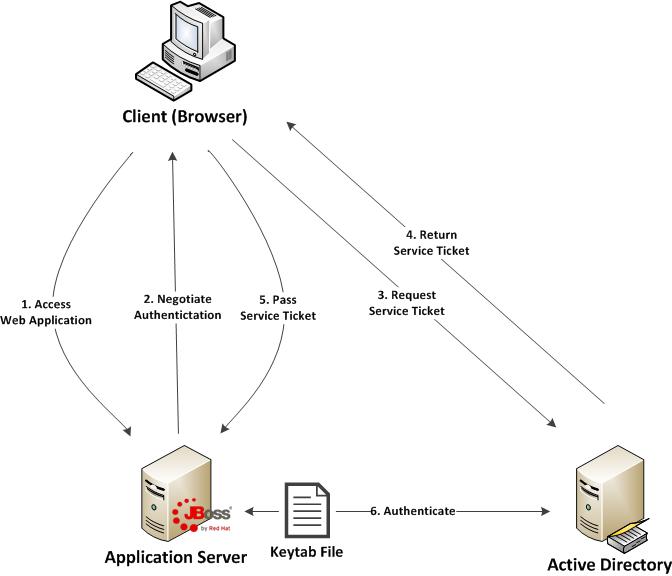
One of the benefits of web applications living in a windows domain is their ability to utilize single sign on and integrated authentication as an authentication mechanism. This functionality is natively supported on Microsoft’s own Internet Information Services (IIS) web server, but can be also employed on non Windows based web servers and applications. In both cases, each leverages an implementation of a negotiation of credentials between the web browser and a server implementing the Kerberos protocol (Active Directory in a Windows environment) called SPNEGO (Simple and Protected GSS-API Negotiation Mechanism). The SPNEGO protocol is used when a client wishes to authenticate to a server, but each are unaware of the security mechanisms that each supports. The client will propose both a preferred authentication mechanism and a set of supported mechanisms. The server will either accept the proposed mechanism, choose from one of the supported mechanisms or reject the authentication request altogether. If both the client (web browser) and the server support the Kerberos authentication mechanism, it will be chosen. Otherwise NTLM can be used as a fallback, though it is less secure and often not a supported mechanism. SPNEGO is supported on a range of Java frameworks and containers such as Spring, Tomcat and JBoss. Its functionality is enabled in JBoss through a component of the PicketLink framework called JBoss Negotiation. Initially as a standalone product, the JBoss Negotiation toolkit provides a Tomcat authenticator and a JAAS login module which enable applications to leverage single sign on. While EJB’s can participate in single sign on, web applications account for the majority of its use case. For a web application to leverage SPNEGO on JBoss, configurations must be made within the web application, the JBoss server, and in Active Directory. Sections of these steps are documented in various locations including the JBoss Negotiation User Guide (Written for EAP 5) and the JBoss EAP 6.1 Security Guide to name a few; however a complete end to end reference is hard to find. This article will discuss the steps involved in configuring a web application to utilize integrated Windows authentication (SPNEGO) on JBoss EAP 6.1.
Before diving in to the specific configurations, let’s discuss the process of how a web application in general is able to obtain the user name of the currently logged in user through integrated authentication. First, a user utilizes a browser to navigate to the web application. The server will respond stating that it must negotiate authentication. If both the browser and server support SPNEGO, it will be used. This is determined by verifying the existence of a trust between the browser and server. Since the browser will be seamlessly passing authentication information about the user to the server, a trust must be configured within the web browser otherwise SPNEGO authentication will not be attempted. If this trust exists, the browser must then contact Active Directory, which is acting as a Kerberos Ticket Granting Service (TGS), and retrieve a Service Ticket (ST) which is used to prove the identity of the caller. This ticket is then sent to the web server. The web server, which is configured within Active Directory to be a Service Principal (SP), uses a keytab file to communicate with Active Directory to decode the ticket and return the desired user name. A diagram of this process is shown below.
Don’t worry if some of these concepts seem unclear. These will be revealed over the course of the discussion. At a high level, the following are the steps required to configure a web application with integrated authentication on EAP 6.1:
- Generate and create a keytab file which will store a Service Principal used by the JBoss Server to authenticate against Active Directory
- Configure the JBoss server
- Configure the web application
- Configure the client web browser
Posted: April 11th, 2013 | Author: sabre1041 | Filed under: Technology | Tags: Errai, GWT, JBoss, OpenShift | No Comments »
One of the prominent features of Java EE 6 was the introduction of Contexts and Dependency Injection (JSR 299). Built on top of Dependency Injection for Java (JSR 330), CDI allowed Dependency Injection (DI) and Aspect Oriented Programming (AOP) to become standardized giving developers the flexibility to implement a native solution rather than having to utilize a third party library such as Spring. CDI makes it easy to inject resources such as managed beans and services. It has done wonders for server side components, but if there is one thing web 2.0 has taught us, more and more functionality is being leveraged on the client side. Java based web frameworks have also moved in this direction as well with implementations such as Google Web Toolkit (GWT) compiling Java code into highly optimized JavaScript. Until now, CDI was restricted to being a server side technology, but with the help of the Errai Framework, CDI can now be leveraged on the browser. Errai is more than a dependency injection toolkit but rather a set of technologies built on top of the ErraiBus messaging framework for developing rich web applications using GWT. In this post, we will demonstrate several components of the Errai framework and how they can be used to build powerful web applications.
To help illustrate the various components of the Errai framework, we will walk through a sample application. This application allows users to perform basic mathematic operations such as addition, subtraction, multiplication and division among others. After a successful submission, the result of the operation is displayed below along with a log of all of the operations they have previously performed. Also included next to each submission is an icon indicating the users’ operating system and browser.

This application was designed specifically for showcasing various Errai components. The source code for this application is found at https://github.com/sabre1041/errai-math which will be useful when we begin discussing the implementation. The application can also be accessed directly as it is deployed on Red Hat’s OpenShift PaaS by navigating to http://erraimath.andyserver.com. The application can be deployed using GWT development mode, JBoss EAP 6 or OpenShift. It utilizes the following Errai components:
- Errai JAX-RS
- Errai CDI
- Errai UI
- Errai Data Binding
We will discuss each component in detail moving forward.
Before we dive into the details of the application, let’s briefly discuss how Errai applications fit into the conventions of a GWT application. A GWT application is configured into Modules which are defined in xml files. These files are placed at the top of the project hierarchy. In our application, the module file is named ErraiMath.gwt.xml. Standalone GWT applications need to also define an EntryPoint class which denotes the starting point for the application in their module file. Errai applications can forgo this requirement by instead annotating a class with the @EntryPoint annotation. Our EntryPoint class is called ErraiMath in the com.redhat.errai.math.client.local package. All client side files will be placed in this package.
Posted: April 7th, 2013 | Author: sabre1041 | Filed under: Technology | Tags: JBoss, jBPM | No Comments »
In our introductory post to jBPM, we demonstrated how jBPM3 can be utilized as a Business Process Management solution. While we did not explore the full potential jBPM3 has to offer, we were able to introduce and examine key features that are present in most BPM solutions. Since its introduction back in 2007, jBPM3 has been a rock star, especially in the SOA Platform. However, many have felt that it was too complex and required a deep understanding of the data model and the API. A number of features would need to be improved for upcoming releases. At the same time, a separate project located on the JBoss community side of the house called Drools Flow attempted to leverage BPM on the Drools Platform. It contained the industry standard Business Process Modeling Notation (BPMN) for modeling processes and Human Tasks based on the WS-HumanTask specification for executing tasks. jBPM4 had improved many of the shortcomings of its predecessor by reworking the process execution engine, but the project was ultimately abandoned after numerous issues arose. After a complete rework, jBPM5 was born as a merge of both the jBPM and Drools Flow. We will forego the discussion on Drools Flow and get right to jBPM5. During the course of our discussion, we will introduce key concepts and walk through a sample application in a similar fashion from the first post. Both applications are identical in functionality which will allow for comparisons between jBPM3 and jBPM5.
Installation and configuration
BRMS 5.3.1 was released in mid December 2012 and is available from both as a standalone application or as a deployable package for JBoss Enterprise Application Platform 5 and 6. Before we can walk through the example application, we need to make sure our local environment is configured properly. These include the following tools:
- Apache Maven
- JBoss Developer Studio 5 (Eclipse with the BPMN plugin can also be used but this post will focus on a JBoss Developer Studio installation)
- JBoss SOA-P
Seeing as our previous discussion on jBPM3 targeted JBoss Service Oriented Architecture Platform 5.3.1, we will install the BRMS deployable package for EAP 5. Obtain the BRMS 5.3.1 deployable package for EAP 5 (not EAP 6) and have the package available on your local machine. You may be able to configure BRMS on EAP 6 and utilize the sample project, but this was not tested.
The BRMS 5.3.1 deployable package contains the following:
- Guvnor Repository Manager
- jBPM5 Console
- Modeshape data store
- jBPM5 library
- BRMS library
Since the necessary artifacts for building BRMS projects are not found in the JBoss public Maven repository, we will use the artifacts found in the jBPM5 library package to populate the our local Maven repository. Extract the contents of the jboss-jbpm-engine.zip to the directory of your choosing. This package contains the necessary jBPM5 artifacts other BRMS artifacts that may be required by the example project. Navigate to the directory you extracted the archive and execute the following commands from the terminal to install the necessary artifacts into your local Maven repository.
mvn install:install-file -Dfile=lib/drools-core-5.3.1.BRMS.jar -DgroupId=org.drools -DartifactId=drools-core -Dversion=5.3.1.BRMS -Dpackaging=jar
mvn install:install-file -Dfile=lib/knowledge-api-5.3.1.BRMS.jar -DgroupId=org.drools -DartifactId=knowledge-api -Dversion=5.3.1.BRMS -Dpackaging=jar
mvn install:install-file -Dfile=lib/drools-compiler-5.3.1.BRMS.jar -DgroupId=org.drools -DartifactId=drools-compiler -Dversion=5.3.1.BRMS -Dpackaging=jar
mvn install:install-file -Dfile=jbpm-workitems-5.3.1.BRMS.jar -DgroupId=org.jbpm -DartifactId=jbpm-workitems -Dversion=5.3.1.BRMS -Dpackaging=jar
mvn install:install-file -Dfile=jbpm-bpmn2-5.3.1.BRMS.jar -DgroupId=org.jbpm -DartifactId=jbpm-bpmn2 -Dversion=5.3.1.BRMS -Dpackaging=jar
mvn install:install-file -Dfile=jbpm-flow-5.3.1.BRMS.jar -DgroupId=org.jbpm -DartifactId=jbpm-flow -Dversion=5.3.1.BRMS -Dpackaging=jar
mvn install:install-file -Dfile=jbpm-flow-builder-5.3.1.BRMS.jar -DgroupId=org.jbpm -DartifactId=jbpm-flow-builder -Dversion=5.3.1.BRMS -Dpackaging=jar
mvn install:install-file -Dfile=jbpm-human-task-5.3.1.BRMS.jar -DgroupId=org.jbpm -DartifactId=jbpm-human-task -Dversion=5.3.1.BRMS -Dpackaging=jar
mvn install:install-file -Dfile=jbpm-persistence-jpa-5.3.1.BRMS.jar -DgroupId=org.jbpm -DartifactId=jbpm-persistence-jpa -Dversion=5.3.1.BRMS -Dpackaging=jar
mvn install:install-file -Dfile=jbpm-bam-5.3.1.BRMS.jar -DgroupId=org.jbpm -DartifactId=jbpm-bam -Dversion=5.3.1.BRMS -Dpackaging=jar
mvn install:install-file -Dfile=jbpm-test-5.3.1.BRMS.jar -DgroupId=org.jbpm -DartifactId=jbpm-test -Dversion=5.3.1.BRMS -Dpackaging=jar
To help illustrate the components of jBPM5, we will utilize the BPMN designer within JBoss Developer Studio 5. This designer is not installed by default in fresh installations and must be installed separately through the JBoss Central console. Navigate to JBoss Central by selecting Help -> JBoss Central. At the bottom of the panel, select the Software/Update tab. Locate the Business Rules Tooling component which contains tools for jBPM, Drools and Guvnor interaction. Check the box next to the component and click Install. Accept any End User Licensing Agreements which might appear, complete the installation and restart JBoss Developer Studio when prompted.
With Maven and JBoss Developer studio configured, the sample project can be obtained from https://github.com/sabre1041/jbpm3-jbpm5. Once the code has been downloaded on your local machine, import the project as an existing Maven project in JBoss Developer Studio.
With the project imported, let’s open up the SampleWorkflow.bpmn BPMN 2.0 compliant file located in the src/main/resources folder. This file is the business process itself. JBoss Developer Studio displays a graphical editor for ease of process creation and manipulation. The raw XML can also be edited by right clicking the file -> Open With -> Text Editor. By opening the file with the BPMN2 process editor, you are presented with the following workflow:


Recent Comments