Posted: October 19th, 2016 | Author: sabre1041 | Filed under: Technology | Tags: Authentication, Jenkins, OAuth, OpenShift | 1 Comment »
Note: This post contains details about components which may be in active development. Please refer to any release notes or documentation as it relates to the current status and supportability
Jenkins, the Open Source continuous integration server, has been included as a supported offering on OpenShift since the release of OpenShift version 3.1. With only a few simple clicks, an entire continuous integration and delivery pipeline for automating and simplifying the application build and deployment process can be created. All a user needs to do is use the OpenShift web console or command line tool, select the Jenkins template, and log in to the deployed Jenkins environment using the password entered or automatically generated. The Jenkins image for OpenShift provides a fully containerize solution supported by plugins specifically designed for integration with OpenShift. One feature that had been missing previously was the ability to leverage OpenShift as a single sign on (SSO) provider and apply the same authentication mechanisms to access Jenkins. As a user attempts to access a protected resource, they are redirected to authenticate with OpenShift. After authenticating successfully, they are redirected back to the original application with an OAuth token that can be used by the application to make requests on behalf the user. A similar approach already exists for the Kibana integrated aggregated logging solution. A newly released Jenkins plugin, called the OpenShift Login Plugin, now provides the support to enable this functionality.
The first step towards implementing this solution is to add the OpenShift Login Plugin to Jenkins. Adding a plugin to Jenkins takes only a few steps. Login to Jenkins and on the left side of the page, select Manage Jenkins and then Manage Plugins. On the Available tab, enter “OpenShift Login” in the textbox to limit the available plugins presented.
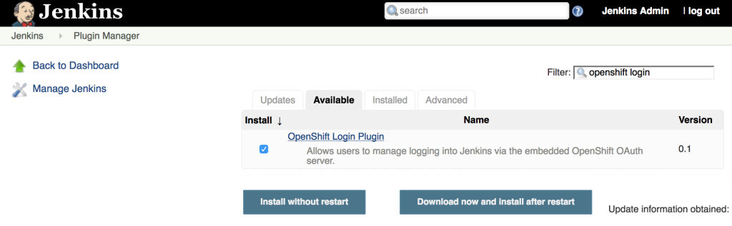
Select the “OpenShift Login Plugin” and click Download Now and Install After Restart. As it’s downloading, be sure to check the “Restart Jenkins when the installation is complete and no jobs are running” so that Jenkins restarts once the plugin has been downloaded. After Jenkins restarts, login once again.
Since the OpenShift Login Plugin interacts with the OpenShift OAuth server to facilitate the single sign on process, Jenkins must be first configured as an OAuth client within OpenShift. There are two ways this can be configured:
- Create a new OAuth client
- Use a service account to represent an OAuth client
The first method is to create a new standalone OAuth client. An OAuthClient is another API object type, similar to other API objects such as a Pod, Service and Route. However, since it is configured at the cluster level, the ability to create or modify is restricted to only elevated users, such as cluster administrators. If your user does not have this level of access, the service account method as described in a subsequent section must be used.
An OAuthClient is represented by a structure similar to the following:
{
    "kind": "OAuthClient",
    "apiVersion": "v1",
    "metadata": {
        "name": "oauth-client-example",
    },
    "secret": "...",
    "redirectURIs": [
        "https://example.com"
    ]
}
When configuring the OAuth client within an application such as Jenkins, the name in the metadata section is analogous to a client_id. The secret is an access credential that is shared with both the authorization server (OpenShift) and the client (Jenkins) and is used to determine trust between each other. Finally, the redirect URI field specifies the location the OAuth server will redirect the user once the authorization process completes (successfully or unsuccessfully).
To simplify the creation of an OAuth client, an OpenShit template has been created to streamline the process and allows for the user to provide values for the OAuthClient name, secret and a single redirect URI. If a secret is not provided, one will be automatically generated.
Execute the following command to add the template to OpenShift.
oc create -f - <<EOF
{
    "kind": "Template",
    "apiVersion": "v1",
    "metadata": {
        "name": "jenkins-oauth-template"
    },
    "labels": {
        "template": "jenkins-oauth-template"
    },
    "parameters": [
        {
            "description": "The name for the oauth client.",
            "name": "OAUTH_CLIENT_NAME",
            "value": "jenkins-oauth",
            "required": true
        },
        {
            "description": "Oauth client secret",
            "name": "OAUTH_CLIENT_SECRET",
            "from": "user[a-zA-Z0-9]{64}",
            "generate": "expression"
        },
        {
            "description": "The name for the oauth client.",
            "name": "OAUTH_CLIENT_REDIRECT_URI",
            "required": true
        }
    ],
    "objects": [
        {
            "kind": "OAuthClient",
            "apiVersion": "v1",
            "metadata": {
                "name": "\${OAUTH_CLIENT_NAME}"
            },
            "secret": "\${OAUTH_CLIENT_SECRET}",
            "redirectURIs": [
                "\${OAUTH_CLIENT_REDIRECT_URI}"
            ]
        }
    ]
}
EOF
The most important parameter, and only required parameter, in the template is the redirect URI. Jenkins exposes an endpoint at /securityRealm/finishLogin that processes the OAuth response and stores the OAuth token for subsequent use. The following command will create the OAuth client by first looking up the hostname of the exposed route and pass the returned value as an input parameter:
oc process -v=OAUTH_CLIENT_REDIRECT_URI=`oc get route jenkins --template='{{if .spec.tls }}https{{ else }}http{{ end }}://{{ .spec.host }}/securityRealm/finishLogin'` jenkins-oauth-template | oc create -f-
Confirm the new OAuthClient called oauth-jenkins has been created by running the following command:
oc get oauthclients
As mentioned previously, if the client secret is not provided during template instantiation, one will be randomly generated. This secret will need to be configured in Jenkins to establish the client/server trust. To locate the secret that was configured in the OAuthClient API object, execute the following command:
oc get oauthclients jenkins-oauth --template='{{ .secret }}'
With the OAuthClient in place, configure Jenkins to make use of the OpenShift Login plugin. Navigate to the Jenkins summary page and click Manage Jenkins and then Configure Global Security. Select the Login with OpenShift radio button to expose several textboxes for further configuration.
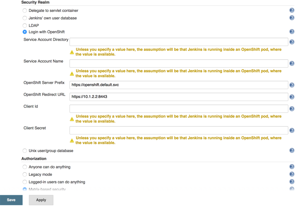
The OpenShift login plugin will attempt to make use of preconfigured variables based on the environment, however, several fields do require manual input. The following fields require modifications:
- OpenShift Server Prefix: Location of the internal OpenShift service (For externally hosted Jenkins servers, utilize the Master API address)
- Enter https://openshift.default.svc
- OpenShift Redirect URL: Location of the OpenShift Master API which will be used to redirect the user to authenticate with OpenShift
- Dependent on the environment. An example could be https://master.example.com:8443
- Client Id: Name of the OAuth Client
- Enter the name of the OAuthClient created previously: jenkins-oauth
- Client Secret. OAuth Client Secret
- Enter the client secret value obtained from the oauth client previously
Click Save to apply the changes. Once the changes have been made, click the logout button on the top right corner of the page. This will trigger a new authentication process and redirect the user to the OpenShift web console to authenticate.
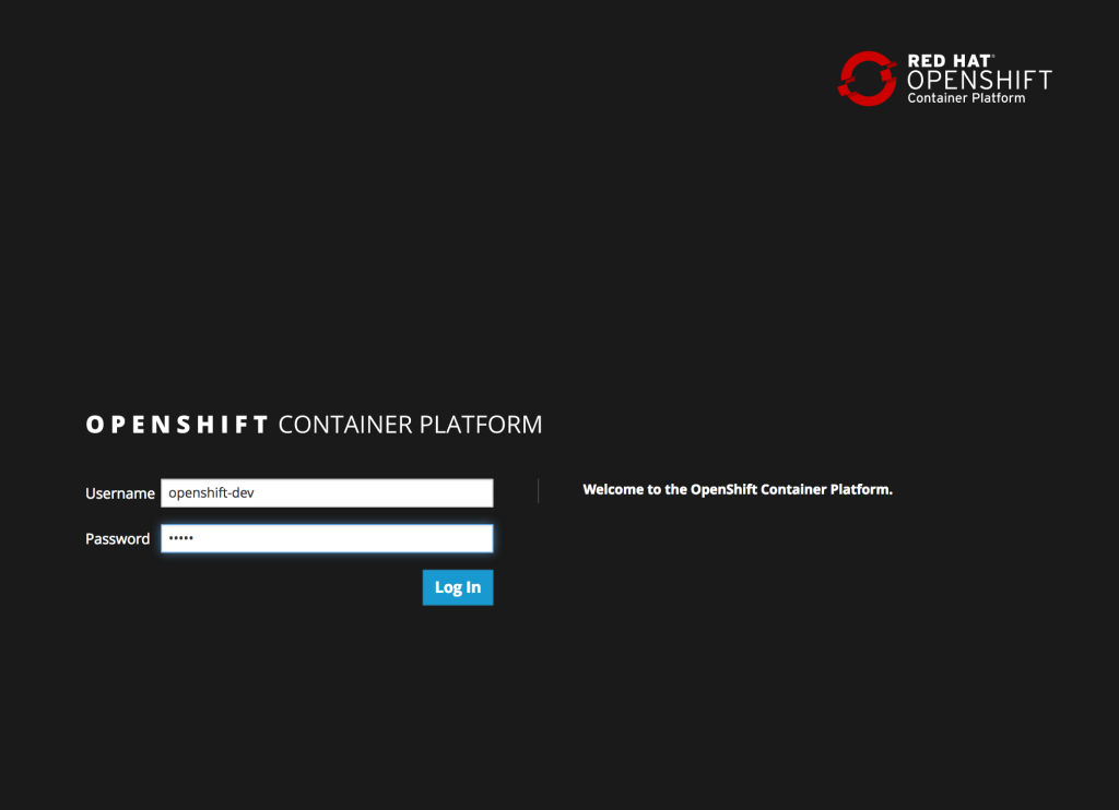
Enter a valid username and password, click Login and authentication will be performed against the realm configured within OpenShift and upon success, the browser will redirect back to the Jenkins home page.
Posted: March 6th, 2016 | Author: sabre1041 | Filed under: Technology | 5 Comments »
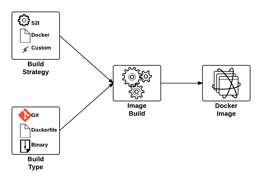
 One of the benefits of a Platform as a Service is the ability for developers to rapidly deploy applications to an elastic, cloud based environment. The application workflow typically involves a developer providing the location of source code in a Git repository that is remotely accessible by the platform for it to retrieve, and to facilitate the build and deployment process. In OpenShift, the two most common build types, Docker and Source to Image (S2I), follow this paradigm. The developer will provide the location of a Git repository, and OpenShift will retrieve the source and perform the build depending on the type. While this workflow is extremely effective, it does require the developer to complete several intermediately steps beforehand, such as allocating and pushing to a Git repository for the platform to pull from. An alternative solution is to utilize another source type supported in OpenShift, called binary builds. Instead of OpenShift using a remote Git repository to pull a source from, the developer directly pushes their content to OpenShift.
This type of build workflow has several benefits developers can take advantage of. First, they can quickly deploy their application to the platform without requiring the allocation of other resources or dependencies, such as a Git repository. Secondly, if the developer has an existing binary artifact, such as precompiled Java web archives (.war), they can deploy it directly to the platform instead of storing it in a Git repository, which is not recommended.
First, let’s understand the entire process behind a binary build in OpenShift. As mentioned previously, the build process is driven by the developer in a push manner, and in most cases, facilitated by the OpenShift Command Line Interface (CLI), which will upload the binary content and start the build process. The start-build subcommand of the OpenShift CLI is used to initiate the entire process. When using a binary build, several types of content can be provided, each with their own subcommand flag: directories, compressed files, or a git repository:
| Content Type |
Subcommand Flag |
|---|
| A system file folder |
–from-dir |
| A compressed file |
–from-file |
| A git repository |
–from-repo |
The builds section of the OpenShift documentation provides a summary of the subcommand options including a list of flags that can be added to further customize their behavior.
With a high level understanding of the binary build process, let’s discuss the steps necessary to configure a binary build. As with all builds in OpenShift, these are set in the BuildConfig object. A typical configuration for a PHP application looks similar to the following:
        {
            "kind": "BuildConfig",
            "apiVersion": "v1",
            "metadata": {
                "name": "${APPLICATION_NAME}",
                "annotations": {
                    "description": "Defines how to build the application"
                }
            },
            "spec": {
                "source": {
                    "type": "Binary",
                    "binary": {
                        "asFile": ""
                    },
                    "contextDir": "${CONTEXT_DIR}"
                },
                "strategy": {
                    "type": "Source",
                    "sourceStrategy": {
                        "from": {
                            "kind": "ImageStreamTag",
                            "namespace": "openshift",
                            "name": "php:5.6"
                        }
                    }
                },
                "output": {
                    "to": {
                        "kind": "ImageStreamTag",
                        "name": "${APPLICATION_NAME}:latest"
                    }
                },
                "triggers": [
                    {
                        "type": "ImageChange"
                    },
                    {
                        "type": "ConfigChange"
                    },
                    {
                        "type": "GitHub",
                        "github": {
                            "secret": "${GITHUB_WEBHOOK_SECRET}"
                        }
                    }
                ]
            }
        },
The most important section in the BuildConfig is the source type in the spec section. In this example, Git is specified as the source type and when a build is run, the contents of the git repository will be cloned into the builder prior to performing the build. To switch over to a binary build type, the source section would look be modified to the following:
"source": {
    "type": "Binary",
     "binary": {
        "asFile": ""
   }
},
The type value is replaced with Binary to indicate the binary build type, and the details of the binary build is entered in a binary section replacing the git section details. The asFile value is used to provide the name of a file containing the binary content that should be created inside the OpenShift builder. Since this field is empty in this example, the contents of the binary source will be extracted into the builder.
Posted: February 14th, 2016 | Author: sabre1041 | Filed under: Technology | No Comments »
In part 1 and part 2 of the series on Jenkins and OpenShift, we used OpenShift as the execution environment to run a Jenkins master instance and a set of either statically defined or dynamically provisioned slave instances. However, many organizations already have an existing Jenkins infrastructure in place to act as the backbone of their continuous integration and continuous delivery pipelines, but they may still desire the ability to take advantage of the elasticity OpenShift can provide. The following outlines the steps necessary for integrating an external Jenkins environment with OpenShift to run jobs.
First, lets review the high level architecture from the first two posts. Each of the master and slave instances are run in Docker containers and deployed to OpenShift as pods. When creating a static set of slave instances, each of the slaves is configured to use Kubernetes services in order to communicate with the master and register itself in Jenkins. The use of Kubernetes services provide a level of abstraction over the actual location of the master since pods, like docker containers, can come and go. Once the slaves have registered themselves with the master, they will be able to take on pending jobs. When leveraging the Kubernetes Jenkins plugin to dynamically provision slave instances, many of the same steps described previously are used, however, instead of statically deploying a set of slave pods, the Jenkins master communicates with the OpenShift API to manage the lifecycle of slave instances. In both paradigms, each use two Kubernetes services to locate and communicate with the master. This is the key area that will need to change when integrating an external Jenkins instance. Instead of the service being configured to point to the Jenkins master in the OpenShift cluster, it will instead be configured to point to the location of the instance externally.
The resources are once again found on GitHub. Clone the repository to your local machine or update it if it is already present:
git clone https://github.com/sabre1041/ose-jenkins-cluster
Next, create a new project in OpenShift either in the web console or on the command line using the oc client called jenkins which will house the resources that will be created:
oc new-project jenkins
Enter the directory containing the Git repository cloned previously and add the three templates to the newly created project
oc create -f support/jenkins-cluster-persistent-template.json,support/jenkins-cluster-ephemeral-template.json,support/jenkins-external-services-template.json
Note: If you followed the steps from an earlier post and would like to reuse the same project, you can either remove or replace the existing templates. using the oc delete template <name> or oc replace -f <files>
The jenkins-cluster-persistent and jenkins-cluster-ephemeral templates are almost identical to the previous postings, A new third template is available to create the service objects to support existing Jenkins instances within the enterprise. Instead of load balancing a set of pods running in OpenShift, the template uses external services to reference the location of the Jenkins master outside of OpenShift.
Lets once again instantiate the template to create a Jenkins master and slave infrastructure in OpenShift. You may be wondering why we would want to leverage a template that creates the Jenkins master in OpenShift when we will be communicating with an externally facing instance. To support both use cases where the master may be running either in OpenShift or externally, we will use the same template and if it is chosen to leverage an external instance, the objects in OpenShift relating to the master can be deleted.
oc new-app --template=jenkins-cluster-ephemeral
The master and slave resources should now created. Since the master components will not be used in OpenShift, let’s go ahead and delete them. The oc delete command can be used to remove objects from an OpenShift project. The -l parameter can be used to target a subset of objects so for our use case, only the master components will be deleted. The template added labels to each of the components that were instantiated in the form application=jenkins to represent the master and application=jenkins-slave to represent the slaves. Execute the following command to remove objects targeting the Jenkins master:
oc delete all -l=application=jenkins
With the existing Jenkins master components now removed, let’s instantiate another template which will create the services necessary to communicate with the externally facing Jenkins instance. The template takes in a parameter called JENKINS_IP which specifies the location of the external Jenkins instance. Run the following command to instantiate the template specifying the IP address of the externally facing Jenkins instance to create the new services:
oc new-app --template=jenkins-external-services -p JENKINS_IP=<JENKINS_MASTER_IP>
Note: If a pod containing a slave instance is currently running, it must be deleted in order to inject the correct service address and port referring to the external Jenkins instance
Posted: January 31st, 2016 | Author: sabre1041 | Filed under: Technology | 1 Comment »
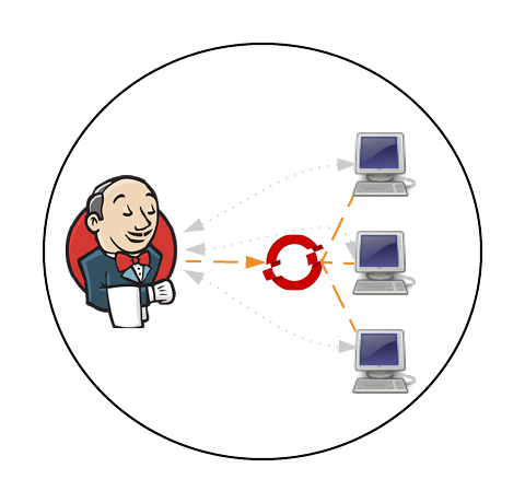
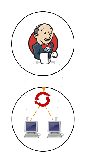
In a previous post, Clustering Jenkins on OpenShift, we introduced how to run the Jenkins Continuous Integration server connected to a collection of slave instances that are used to run Jenkins jobs, all within OpenShift. The slave instances were configured as a pool of running Docker containers that are automatically discovered by the Jenkins master through the use of the Jenkins Swarm plugin. This pool could be scaled up or down as necessary and provides the ability to handle the most robust workload that is only capped by the resource limitations of the cloud infrastructure. While this approach gives administrators the flexibility to define the state of their infrastructure, it can result in wasted resources as slaves become idle waiting to take on incoming job requests. An alternative approach is for the Jenkins master to dynamically provision slave instances as necessary within the OpenShift environment. This process is facilitated by the Jenkins Kubernetes plugin and in a few short steps, Jenkins can be configured to run jobs using dynamically provisioned slaves or complement a set of existing statically defined slaves using the Swarm plugin as described earlier.
Prior to creating any resources within OpenShift, let’s discuss the components involved in being able to dynamically provision Jenkins slave instances.
Note: I will forego a discussion on the topics of Jenkins masters and slaves. I suggest reading the previous entry which provided an overview of these concepts.
When using the Jenkins swarm plugin as in the previous post, slave instances were provisioned by OpenShift in a predetermined manner similar to any other application deployment. The number of slave instances can be governed by project members or cluster administrators . These instances are configured with the parameters necessary to communicate with the Jenkins master, which in turned allowed them to register themselves to take on workload. The registration and discovery of the slaves does provide a substantial benefit to Jenkins administrators as they no longer needed to manually configure the slave instances within Jenkins. However, when working with the Kubernetes plugin, the responsibility to provision new slave instances belongs to the Jenkins master and is based on the current workload of the master. When the Jenkins master determines that there is a need for additional resources to perform jobs, it will utilize a preconfigured Docker image to perform the job. The plugin communicates with the Kubernetes (OpenShift) API to create a new container/pod. Using the parameters automatically specified by the plugin to start the container, the slave has all of the information that it needs to communicate back with the master to complete the registration and to perform the job. Once the job completes, the slave is then destroyed.
Posted: January 3rd, 2016 | Author: sabre1041 | Filed under: Technology | 4 Comments »
Note: OpenShift version 3.4 now provides support for executing dynamic slaves within the platform. More information can be found here
A Continuous Integration server can act as a focal point for managing the builds and deployments of applications. As organizations adopt many of the principles of Continuous Integration and Continuous Delivery, the stability of a continuous integration server, such as Jenkins, becomes magnified. The majority of the components within Jenkins that most users are familiar with, such as the user interface and job configuration and execution, occurs on the Jenkins master. However, the execution of these jobs can be delegated to external agents, called slaves, to offload processing from the master. The utilization of slave agents is a natural progression many organizations move towards as they expand their Jenkins usage. Slaves are nothing more than instances that run a small Java program that communicates with the master to perform job execution. There are several strategies for configuring and managing slaves. The default implementation is to configure a slave on the master and have the master manage the lifecycle of the slave. While this process works and is the most straightforward, the time that it takes to configure and provision slaves is time consuming as there are a number of manual steps that needs to occur on both the master and the slave instances. Another strategy is for slaves to advertise and register themselves to the master. This is accomplished using the Jenkins Swarm plugin and is even more beneficial when working in a cloud environment, such as OpenShift, as slave instances can be dynamically allocated and scaled as necessary. Let’s walkthrough how jobs in Jenkins can be executed using a cluster of slave instances all running in OpenShift.
First, let’s review the architecture of this implementation. Since OpenShift runs Docker containers, both the master and slave instances will each be running as Docker containers within OpenShift. There is no requirement that both the slave and master components needs to be running in OpenShift. But for simplicity, this is the architecture that will be described. Many organizations leveraging OpenShift as their Platform as a Service still utilize an existing Jenkins instance outside of OpenShift and I will cover how you can extend this demonstration to handle that use case. The project can be found on GitHub and contains the resources for adding the Jenkins master and slave components to an OpenShift environment.
https://github.com/sabre1041/ose-jenkins-cluster
Red Hat provides a supported Jenkins Docker image that can be used within OpenShift, and that is what we will use as the base for the image representing the Jenkins master. The only modifications that will need to be added to the master is the inclusion of the Swarm plugin. The docker image containing the slave is a Red Hat Enterprise Linux image with the addition of Swarm client. Additional build tools, such as Maven, can be added to extend the functionality of the slave, but was omitted from this demonstration. Feel free to fork and extend and/or modify to suit your specific use case. The benefit of the swarm plugin is that slaves can come and go without any manual configuration on the master. By default, the master discovers slaves with Jenkins Swarm plugin using UDP broadcast. However, in our case, slaves connect directly to the master. The Jenkins master listens for incoming slave connections on port 50000. Within OpenShift, containers can communicate with each other using Kubernetes Services. A Kubernetes service is an network abstraction over a group or pods, or containers deployed on the same host. Two services have been defined in this implementation:
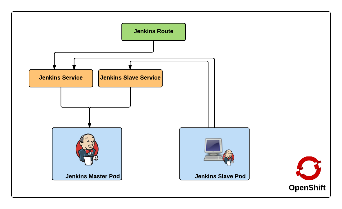
- jenkins – Load balances requests to the Jenkins master for the Jenkins UI on port 8080
- jenkins-slave – Load balances requests to the Jenkins master for agent communication on port 50000
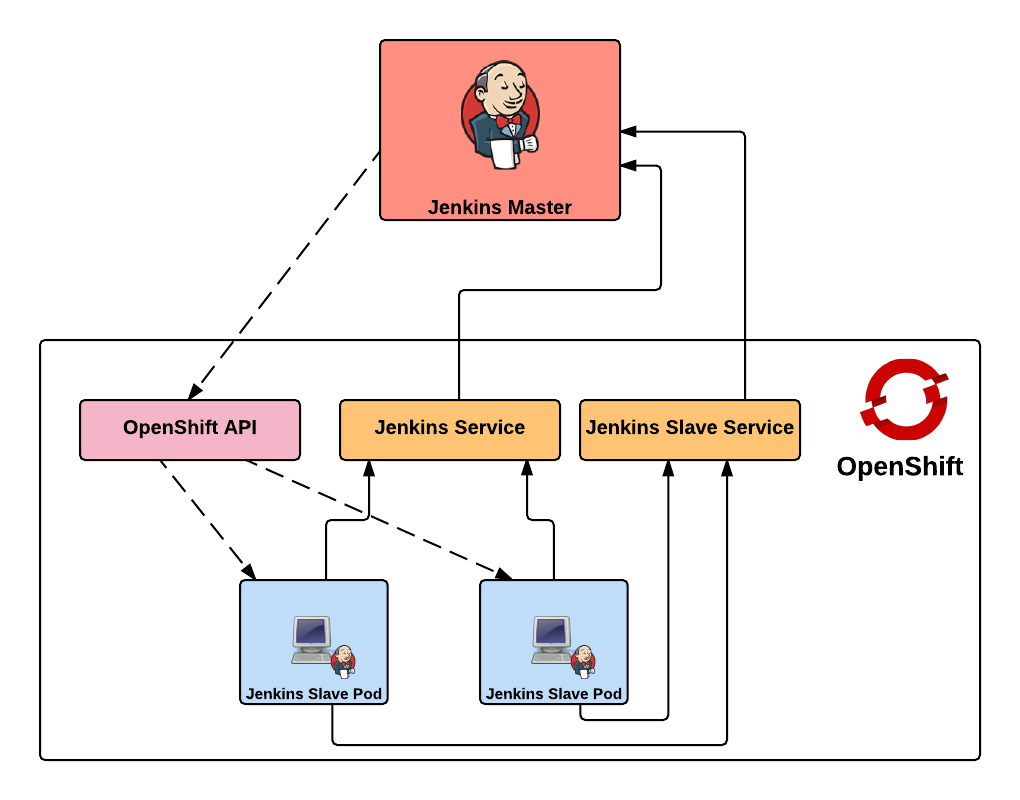
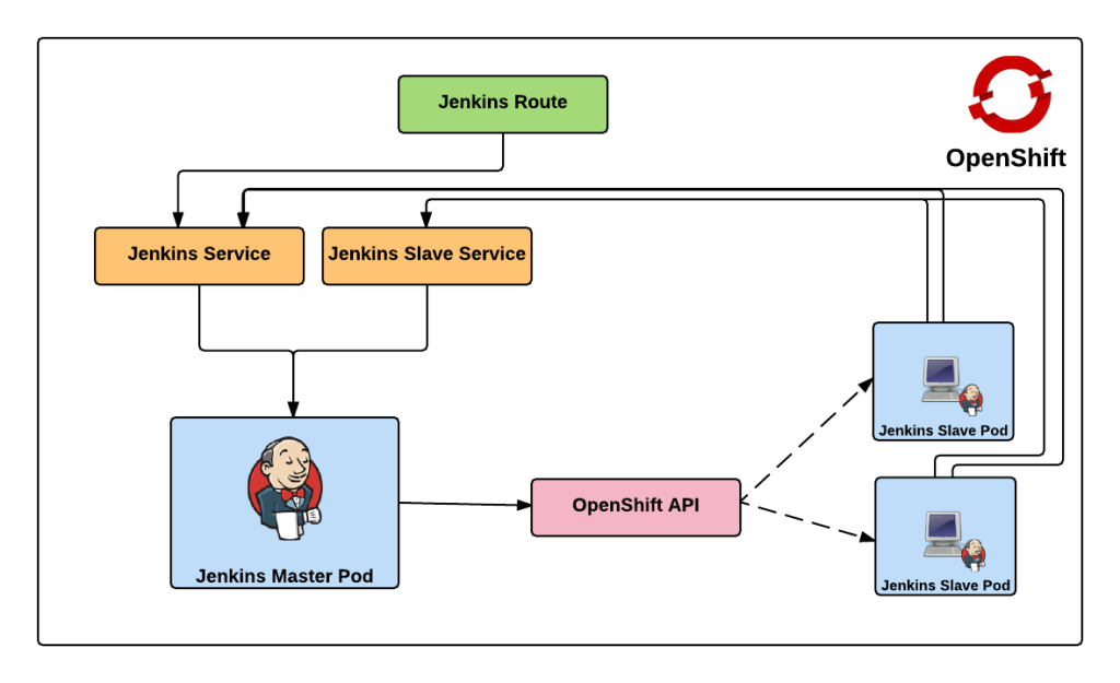
Both of these services enable the slaves to communicate with the master. Kubernetes services expose environment variables that can be consumed by pods.The slave docker image uses a wrapper script to start up the java process containing the slave agent where these environment variables are referenced along with additional parameters such as the user name and password that will be used to connect to the master as well as the number of build executors. We will see how we can configure and manage these properties later on. Also included in the repository are two OpenShift templates that allow for the cluster to be instantiated with ease. The difference between the two templates is that one provides support for persistent storage. More information on persistent storage can be found in the OpenShift documentation. The following diagram depicts architecture created by the template.
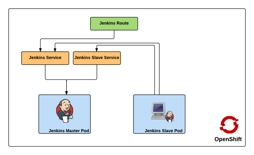
The Jenkins route is used to handle requests from outside the OpenShift environment, such as a typical user accessing the Jenkins user interface which is then passed down to the service and then ultimately into the master pod. Now that we have an understanding of the architecture created by the template, lets discuss how to create and run the Jenkins cluster within OpenShift. To get started, first clone the repository to your local machine
git clone https://github.com/sabre1041/ose-jenkins-cluster
If an OpenShift project is not already created, create a new project for Jenkins
oc new-project jenkins
Enter the directory containing the Git repository cloned previously and add the templates to the project
oc create -f jenkins-cluster-persistent-template.json,jenkins-cluster-ephemeral-template.json
Both templates should now be available in the project. Let’s instantiate the jenkins-cluster-ephemeral template (Note: This template does not use persistent storage for the master. All settings and configurations will be lost once the pod dies)
oc new-app --template=jenkins-cluster-ephemeral
New builds of both the Jenkins master and slave images will be started. You can track the progress by executing the following command:
oc get builds
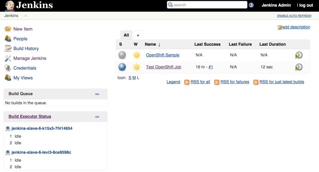
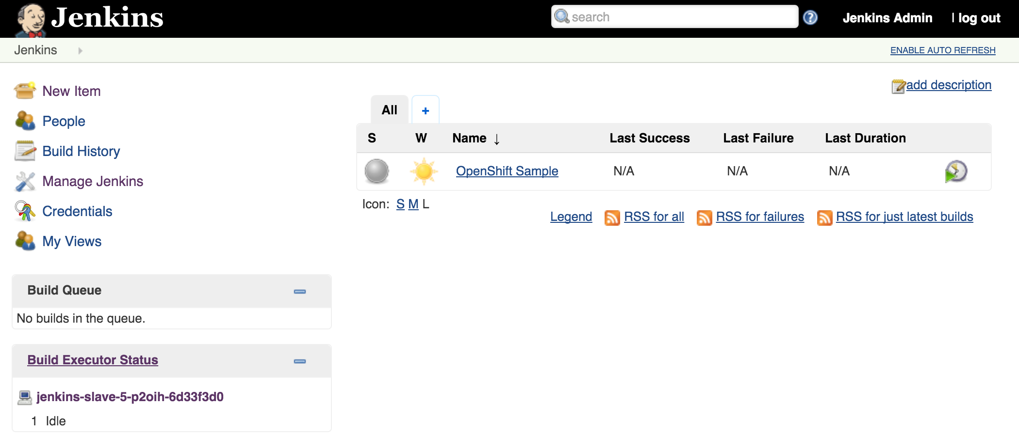
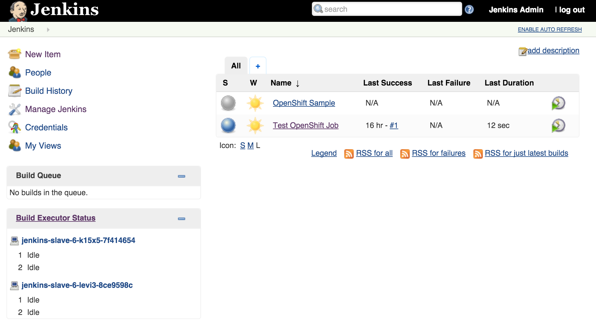
Once the builds complete successfully, the new docker images will be pushed to the integrated registry and new containers will be launched. The Jenkins user interface can then be accessed at http://jenkins.<project>.<default-domain-suffix>. The default username and password is admin:password. Once authenticated, you are presented with the Jenkins main user interface containing a list of jobs. The default Jenkins image from Red Hat contains a sample job called “OpenShift Sample”. While we will not be utilizing this job, feel free to explore how it can be used in conjunction with OpenShift to create a continuous integration and continuous delivery process. On the left side of the page, you will see a list of build executors. This section is where Jenkins slaves will be listed. Since the template configured the build of a docker image and ultimately deployed a container, you should see one slave agent that has automatically connected to the Jenkins master using the Swarm plugin.

Since there is an available executor to run jobs as it is currently idle, lets create a very simple Jenkins job to validate the setup. On the left side of the page, select New Item Enter a name for the job, such as Test OpenShift Job, select Freestyle Project and then click OK to create the job. A freestyle project will then be created and then take you to the configuration page. Configure a somewhat trivial implementation that will pause for 10 seconds that will allow for the job to be validated running on the slave and then print “hello world” to the console. Still on the job configuration page, click Add Build Step and then Execute Shell. Enter the following into the textbox
sleep 10
echo "Hello World"
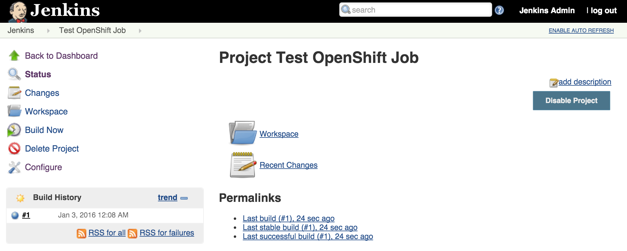
Click Save to apply the job configuration Run the job by hitting Build Now on the lefthand side. A new build will be scheduled on the slave and once complete, it will be available in the build history dialog

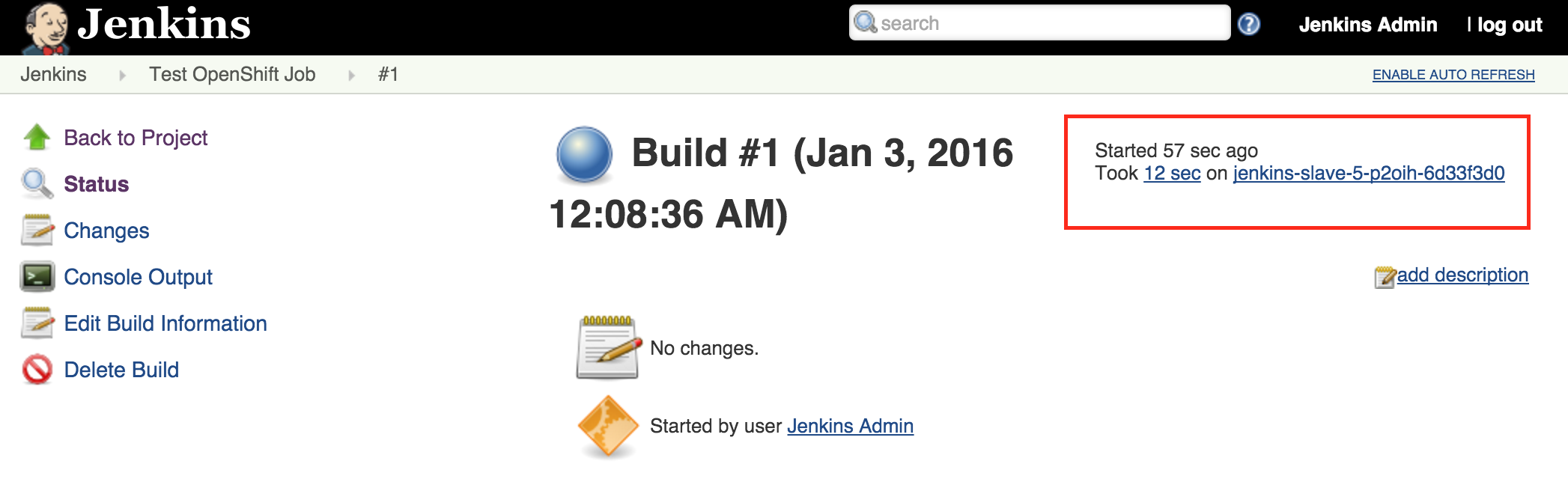
View the result of the first job execution by clicking #1 under the build history. On the top right corner, the location of where the build occurred should be visible.

With the job running successfully on the slave, lets discuss how OpenShift will be able to help handle increased load on the slaves in the future. One of the benefits of running within OpenShift is the ability to scale with ease by increasing the number of slave instances that are deployed into the cluster. To scale up the number of slaves, increase the number of replicas on the deploymentConfig.
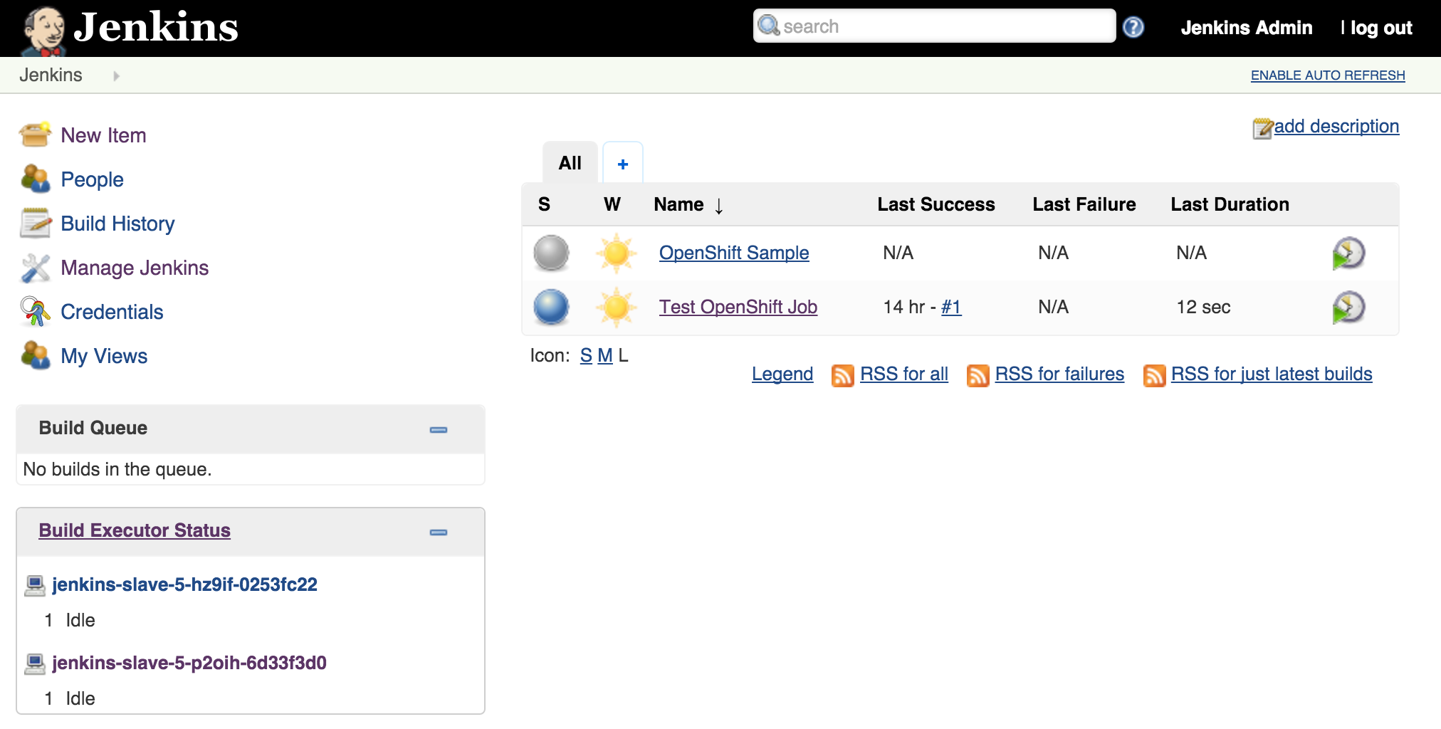
oc scale dc jenkins-slave --replicas=2
As we saw earlier, new slave instances will automatically discover and register themselves to the master. With a second slave instance created, refreshing the Jenkins user interface should not show both slaves registered:

Increasing the number of slave instances is one way to manage job load from the master. Alternatively, instead of adding additional slave instances, the number of executors within each slave can be manipulated. This will allow for multiple jobs to be run concurrently on each slave. The number of executors that a slave allocates is specified in the wrapper script by reading the value of the EXECUTORS environment variable which is defined in the OpenShift Deployment Configuration. By default, this value is specified to be one. To increase the number of executors for each slave, execute the following command:
oc env dc/jenkins-slave EXECUTORS=2
This will cause a redeployment of the Jenkins slaves as the Deployment Configuration was changed. Refresh the Jenkins user interface to show two executors are now available under each slave.
The ability to manipulate either the number of slaves instances and the number of executors within each slave allows for greater control managing job resources within a Jenkins environment. The combination of the Jenkins Swarm plugin running in an OpenShift environment provides the stability and reliability for a robust continuous integration environment.
Posted: September 8th, 2015 | Author: sabre1041 | Filed under: Technology | Tags: OpenShift, Swagger | 1 Comment »
Several months ago, an article was published by OpenShift lead engineer Clayton Coleman on how the OpenShift API can be expressed using Swagger. For those who have never heard of Swagger previously, it is a framework for describing and producing a visualization of a RESTful API. The post gave users an excellent introduction to the resources exposed by OpenShift. Fast forward a few months, and now that OpenShift has been officially released, it is a fine time to revisit Clayton’s post and provide updates to allow users to interact with the GA version of the the product and cover any necessary configurations that need to be made beforehand.
First, let’s revisit the OpenShift architecture and how the Swagger framework is integrated into the product. Two restful endpoints are exposed by OpenShift: The Kubernetes API and the OpenShift API. Each provide decorated swagger endpoints which can be accessed at the following locations:
Kubernetes API:
https://<openshift_master>:8443/swaggerapi/api/<api_version>/
OpenShift API:
https://<openshift_master>:8443/swaggerapi/oapi/<api_version>/
The cURL command can be used to validate the endpoints against an existing OpenShift environment which will produce a Swagger formatted json result. The power of the Swagger framework is realized by the ability to take this API representation and present it in a consumable form for the user to interact with such as retrieving results and invoking requests. These interactions are facilitated using the Swagger UI.
User Interface
The Swagger UI is a set of HTML, CSS and JavaScript components that produce the representation of the API. An updated customized Swagger UI implementation is available to communicate with OpenShift and can be found at http://openshiftv3swagger-sabre1041.rhcloud.com/.
Since the Swagger UI is a client based application that may be served from a domain other than OpenShift, settings within OpenShift would need to be configured on the master to allow for Cross-origin resource sharing (CORS). The OpenShift master configuration file located at /etc/openshift/master/master-config.yaml contains the key coorsAllowOrigins which defines the origins that are allowed to invoke the API. To allow all origins, add a – “.*” to the list similar to the following:
corsAllowedOrigins:
  - 127.0.0.1
  - localhost
  - ".*"
Restart the OpenShift service on the master to apply the changes:
systemctl openshift-master restart
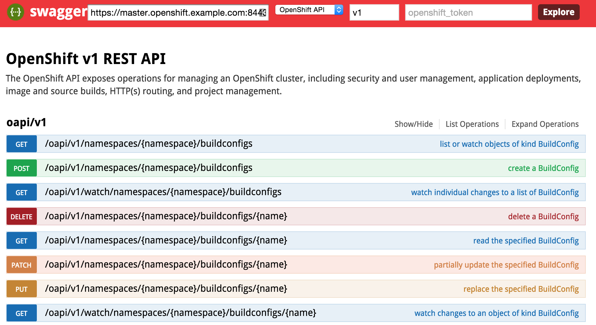
Return back to the Swagger UI and you will notice several input fields at the top of the page which correspond to the following fields:

- Master Base URL – URL (host and port) of the OpenShift Master
- API Type – Type of API to invoke (Kubernetes or OpenShift)
- API Version – Version of the OpenShift API (use v1 for OpenShift V3 GA)
- Authentication Token – User token of a privileged user to execute commands as (explained later)
The endpoint is unsecured by default so listing the functions can be completed without entering a token. First, enter the URL of your OpenShift master. For example, this could be https://master.openshift.example.com:8443. Next, select the API to invoke (either the Kubernetes or OpenShift API) from the dropdown. Then enter the api version in the next textbox (A dropdown of values is available to aid with input selection). Then hit the Explore button. It may take a moment for the page to render, but once finished, the list of functions for the selected API should be presented.

Consult the Swagger documentationfor the full range of capabilities provided by the the framework.
Authentication Token
Many of the API functions require an authenticated user for invocation. An authentication token can be obtained from a user registered in OpenShift to invoke additional functions in the swagger UI. The token can be obtained using the OpenShift CLI from a developer machine.
Assuming the CLI tools have been previously installed, first login to OpenShift
oc login https://<openshift_master>:8443
After successfully authenticating, obtain the token for the session
oc whoami -t
The token value should be provided. Enter this value in the token textbox in the Swagger UI to allow for the execution of additional resources the user is authorized to invoke.
The source code for the project is located at https://github.com/sabre1041/openshift-api-swagger and contributions are always welcome.
Posted: June 24th, 2015 | Author: sabre1041 | Filed under: Technology | Tags: Fuse, JBoss, Security | No Comments »
 One of the features introduced in JBoss Fuse 6.2 is the ability to utilize Role Based Access Control (RBAC) to govern the capabilities authenticated users have when interacting with the container. RBAC is important because it allows for a delineation of the roles and responsibilities of users managing the Fuse container to exist. For example, a team may have a set of individuals who manage the configuration of the container including all deployed applications in a system administrator role while another team may have a set of individuals whom have the responsibility for monitoring the state of deployed application. RBAC provides the ability to restrict access to the monitoring team to only view the state of the container in a read only manner while providing unrestricted access to the administrator team. Fuse and the underlying Karaf container provide a flexible framework for configuring and managing Role Based Access Control configurations. RBAC was initially introduced in Karaf 3.0.0 and subsequently ported back version 2.4.0 for which Fuse is based off of.
Fuse provides a number of standard roles that can be applied to users. These roles are defined in the following table:
| Roles |
Description |
|---|
| Monitor, Operator, Maintainer |
Read only access |
| Deployer, Auditor |
An appropriate level or read-write access who want the ability to deploy and run applications, but blocks access to sensitive container |
| Administrator, SuperUser |
Unrestricted access to the container |
The enforcement of Role Based Access Control in Fuse is accomplished with the help of two mechanisms: JMX Guard and OSGi guard. JMX guard is a mechanism that is configured at the JVM level to intercept all invocations made against the JMX interface, similar to a Servlet Filter. As an invocation is made, JMX guard verifies the requestor has the appropriate permissions and based on the assentation, they are either granted access to the resource or denied. OSGi guard on the other hand governs the ability to invoke methods on an OSGi service in the form of a proxy between the client and the service. Both JMX and OSGi guard use Access Control List’s (ACL’s) for declaring the methods and services that are to be secured and the roles that have access. All of the ACL files are located within the etc/auth folder of Fuse. There are two types of ACL’s, JMX and command based. Default configurations have been provided, but you are free to modify and customize as necessary.
There are four primary locations where RBAC is enforced:
- JMX – Direct invocations are protected by JMX Guard
- Fuse Management Console – Communicates using REST via Jolokia technology. Since Jolokia it is situated on top of the JMX, it affords the same protection that JMX provides
- Karaf commands – Enforcement is provided whether commands are entered on the virual terminal in the Fuse Management Console, remote connection via SSH or using the CLI
- OSGi Services – Protections against invocations of individual methods
Applying roles to users is dependent on the authentication scheme being used. By default, Fuse comes enabled with the PropertiesLoginModule which utilizes a configuration file located at etc/users.properties to define the authentication and authorization of users. Users can be added one line at a time in the file in the following format:
username=password,role1,role2…
For example, to configure a user called monitor with password monitor and the role Monitor, it would appear in the following format:
monitor=monitor,Monitor
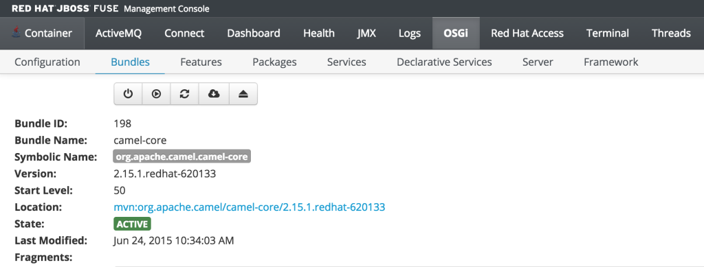
As previously discussed, users who have the monitor role have a read only view of the container. To validate proper enforcement of this role to this newly created user, start up the Fuse container and navigate to the Fuse Management Console at http://localhost:8181. Enter monitor for both the user name and password and click login to access the console. Navigate to the OSGi tab to view the current status of the components running in the OSGi container. The list of installed bundles within the container are shown by defaults and can be sorted and filtered if desired. Select the camel-core bundle. When logged in as a user with access to modify components, a dialog is available for starting, stopping, updating and refreshing the bundle as shown below:
But since the monitor user only has read access, this dialog will not be present and the view will appear as the following:
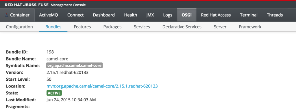
This type of read only protection is also extended to other core components of the Fuse Management Console such as ActiveMQ and Camel JMX pages and can be further customized. With the inclusion of Role Based Access Control support, it is now even easier to manage and govern access to the JBoss Fuse platform. A full description of the features and capabilities of Role Based Access control can be found in the JBoss Fuse product documentation.
Posted: April 1st, 2015 | Author: sabre1041 | Filed under: Technology | Tags: Camel, Docker, Integration, Spring Boot, Websockets | 1 Comment »
Software today is being developed and released at a breakneck pace. No longer are organizations relying on a yearly, quarterly or monthly release cycle, but can now churn out multiple releases daily or even hourly. Two technologies that help facilitate this type of delivery model are Spring Boot and Docker. Spring Boot provides a lightweight microcontainer architecture for rapid development and deployment. It takes a Configuration over Convention approach to application development by leveraging resources on the java classpath to configure the application, which are then packaged into an executable jar. Since Spring Boot contains an embedded web container, an external container such as Tomcat is not required (Spring boot can be packaged into a traditional archive for deployment if desired). Docker on the other hand is one of the fastest growing technologies today and has changed the way many organizations package and deploy applications. It allows for an entire application environment to be assembled into images and deployed within containers. Docker Images are typically small in size and the creation of container is extremely fast compared to traditional virtualization technologies enabling rapid deployment and portability across machines.
With the recent release of version 2.15.0, the Apache Camel project now provides direct integration and support for both Spring Boot and Docker. The spring-boot component allows for the Camel context to be autoconfigured by components and configurations from a spring boot application. This includes the auto detection of Camel routes and injection of spring boot properties for use within Camel. The Camel Docker component communicates with the Docker daemon through the Docker rest API and exposes operations such as manipulating Docker images and containers within Camel to be notified when events within Docker occur. To illustrate the integration with these technologies along with several other components released in recent versions of Camel, a sample application has been developed.
The sample application is called spring-boot-docker-camel application can be found on GitHub
There are two primary goals of the application:
- Expose statistics from Docker such as listing images and containers
- Expose events originating within Docker
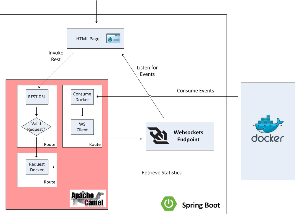
To facilitate user interaction with the application, a web page will be configured to allow users to view events from the Docker daemon in real time and also provide links to retrieve statistics from Docker. Instead of invoking the Docker rest API directly, Camel will be positioned to proxy the requests and expose a restful interface. Camel makes it easy to create restful endpoints by providing a DSL for creation and configuration. Since it is desired for events from Docker to be viewable on the web page, careful considerations should be made on the most efficient method to architect the solution. A polling mechanism to a Camel endpoint could be implemented by the web page, but this would be an expensive operation with regards to network traffic, as the majority of the requests would result in no consumable responses. On the other hand, if websockets were utilized, the amount of network traffic between the client and the server could be drastically reduced and be more efficient as the client would receive a response from the server immediately as an event occurs instead of waiting for the next polling interval. Spring Boot provides the capabilities to define and publish websockets endpoints that Camel can publish events to. Lets step through each aspect of the application to get a better understanding of the components involved and how they are able to integrate with each other.
Posted: September 22nd, 2014 | Author: sabre1041 | Filed under: Technology | Tags: Fuse, OSGi, Testing | No Comments »
 As developers, we are cognizant that testing is a critical component of the development process. In a previous post, we demonstrated the importance of testing applications in a remote container using the Red Hat JBoss Fuse platform and JBoss Developer Studio (Eclipse). The process of remote debugging is a form of integration testing. While the majority of testing is primarily composed of unit testing in an isolated environment, integration testing affords the developer the ability to validate their application with the systems they will interact with. When developing OSGi applications, there are several integration testing frameworks to choose from. Pax Exam has established itself as one of the most popular due to its flexibility and support for multiple container types including Apache Karaf, the underlying platform for JBoss Fuse. Integration tests using Pax Exam can simulate functionality not only within the base OSGi container, but also integrate with other core Fuse platform components including Apache Aries Blueprint and Apache Camel. Fuse provides template applications as a starting point for developers to begin creating applications of their own. These typically consist of a project, ready to be deployed to the Fuse container, along with unit tests to validate expected outcomes and to demonstrate unit testing of Fuse technologies. One area which unfortunately lacking is these templates is the use of integration testing. The following will introduce a template application that demonstrates the use of integration testing in JBoss Fuse platform technologies using Pax Exam.
The majority of applications designed for the Fuse platform are built using Apache Maven. Maven is not only the recommended build tool, but is also used by the Fuse platform itself for dependency resolution. It comes as no surprise that Fuse template projects utilize Maven Archetypes, the project templating toolkit for Maven. To be consistent with the Fuse template projects, Maven Archetypes were utilized to demonstrate Pax Exam integrating testing and the Fuse platform. The actual creation of Maven Archetypes is beyond the scope of this discussion, be we will walk through one of the resulting generated projects to demonstrate how you can begin to use Pax Exam for your own integrating testing needs, and to validate these types of applications that can be deployed to the Fuse platform.
First, ensure you have the appropriate tooling installed and configured on your machine. Git and Maven are the two pieces of required software. Full instructions on installation and configuration can be found on their respective websites. It is also recommended that an IDE such as JBoss Developer Studio/Eclipse be installed. This is suggested, though not required. Next, clone the Git repository containing the archetypes onto your local machine.
git clone https://github.com/sabre1041/fuse-archetype-pax-exam.git
With the repository available on your machine, build and install the included archetypes into your local maven repository by navigating to the location where the git repository was cloned and executing the following command:
mvn clean install
Now that the archetypes are installed in your local Maven repository, let’s walk through one of the included projects. One of the most basic Fuse sample projects demonstrates the use of a Camel route within a Blueprint project. As with other Fuse sample projects, the Camel blueprint project can be easily deployed to the Fuse platform and also demonstrates the use of a unit test. We will swap out the unit test in favor of a Pax Exam integration test as part of our template project. Lets go ahead and generate and walkthrough the analogous template project with Pax Exam integration testing. We will generate a project based on the Maven Archetype with the following Maven properties:
- Group ID: com.redhat.fuse
- Artifact Id: camel-blueprint-pax-exam
- Version: 0.0.1-SNAPSHOT
Note: The following set of commands assumes the above values have been configured. If you choose to use your own values, be sure to substitute them accordingly.
Navigate to a directory where you would like the resulting project to be generated and run the following command:
mvn archetype:generate -DinteractiveMode=false -DarchetypeGroupId=com.redhat.fuse -DarchetypeArtifactId=camel-archetype-blueprint-pax-exam -DarchetypeVersion=1.0.0 -DgroupId=com.tgt.fuse -DartifactId=camel-blueprint-pax-exam -Dversion=0.0.1-SNAPSHOT
A Maven project will be created in a folder called camel-archetype-blueprint. At this point, the project can be loaded into an IDE such as JBoss Developer Studio. The project itself is quite simplistic. A Camel route is triggered every five (5) seconds which prints a message to the Fuse server log. This can be seen by inspecting the blueprint descriptor file located at <PROJECT_ROOT>/src/resources/OSGI-INF/blueprint/blueprint.xml.
  <camelContext id="blueprintContext" trace="false" xmlns="http://camel.apache.org/schema/blueprint">
    <route id="timerToLog">
      <from uri="timer:foo?period=5000"/>
      <setBody>
          <method ref="helloBean" method="hello"/>
      </setBody>
      <log message="The message contains ${body}"/>
      <to uri="mock:result"/>
    </route>
  </camelContext>
In the original implementation, a JUnit test using the Camel blueprint testing framework is utilized. The source for this test can be found at the following location.
https://github.com/apache/camel/blob/master/tooling/archetypes/camel-archetype-blueprint/src/main/resources/archetype-resources/src/test/java/RouteTest.java
Posted: September 1st, 2014 | Author: sabre1041 | Filed under: Technology | Tags: Eclipse, Fuse, JBoss Developer Studio, Testing | 2 Comments »
 Testing is one of the primary components of the software development process. It ensures a particular piece of functionality matches a desired expectation. Testing can occur in several forms ranging from unit testing, integration testing, and regression testing to name a few. When developing applications for the JBoss Fuse platform, each of these methodologies can be applied. The JUnit framework can be used to perform unit testing where direct support is made possible from key Fuse components such as Blueprint and Apache Camel. Pax Exam can be used to perform in container testing and validate functionality against a Karaf environment, the underlying container behind Fuse. While each of these methods provides some assurance against the expected functionality of a particular piece of software, many times a developer may want or even need additional assurance by running and testing their software in an actual application container. Fortunately, Fuse provides methods for interacting with the container in a remote fashion. Remote application debugging is not a new concept. Support is available from some of the most popular integrated development environments including NetBeans, IntelliJ and Eclipse. Since JBoss Developer Studio, an Eclipse variant, is the supported development environment for Fuse, we will focus on how to perform remote application debugging using Eclipse.
Starting Fuse in Debug mode
Prior to being able to connect to Fuse from a remote application, Fuse must be configured to accept remote application connections by placing it in debug mode.
Two methods are available to place Fuse into debug mode:
- Start the Fuse container with the debug option set
- Set the KARAF_DEBUG environment variable to true
The simplest method for starting Fuse in debug mode is to start Fuse with the debug option set. To do so, browse to the <FUSE_HOME>/bin folder and start the Fuse container as follows:
Linux or Mac:
./fuse debug
Windows:
fuse.bat debug
During container initialization, Fuse will also check for the presence of the KARAF_DEBUG environmental variable. If the variable has been defined and is set to true, Fuse will start in debug mode. Environmental variables can be defined on the terminal or command line as follows:
Linux or Mac:
export KARAF_DEBUG=true
Windows:
set KARAF_HOME=true
From the same terminal session, the Fuse container can be started without any additional parameters as described earlier. The one shortcoming to this method is that once the terminal session ends, the environment variable is lost and Fuse will no longer be placed into debug mode the next time it is started. To have Fuse consistently start in debug mode, the KARAF_DEBUG environment variable should be set permanently according to your particular operating system.
Remote access in the Fuse container is made possible through the use of the Java Debug Wire Protocol (jdwp). If Fuse has been set into debug mode, it will by default expose port 5005 for remote access which can be verified by observing the following in the server logs during startup.
Listening for transport dt_socket at address: 5005
If the KARAF_DEBUG environment variable has been set, the full set of debug options will be printed:
karaf: Enabling Java debug options: -Xdebug -Xnoagent -Djava.compiler=NONE
-Xrunjdwp:transport=dt_socket,server=y,suspend=n,address=5005
Listening for transport dt_socket at address: 5005
These parameters can be customized by setting the JAVA_DEBUG_OPTS environmental variable. A full discussion the Java Debug Wire Protocol and the options that can be set is found here.
Debugging from JBoss Developer Studio
Once Fuse has been placed into debug mode and capable for accepting remote connections, an application can be debugged within JBoss Developer Studio against the running Fuse container. Open JBoss Developer Studio to a workspace of your choosing. Determine any areas in which you wish to debug and set breakpoints that will suspend the running application when the line of code is hit during the execution of the application. With the appropriate breakpoints set, select the project you wish to debug in the project view and select Run -> Debug as -> Remote Java Application from the menu bar. If your Fuse container is running and has been placed into debug mode, JDBS will prompt with the following menu:
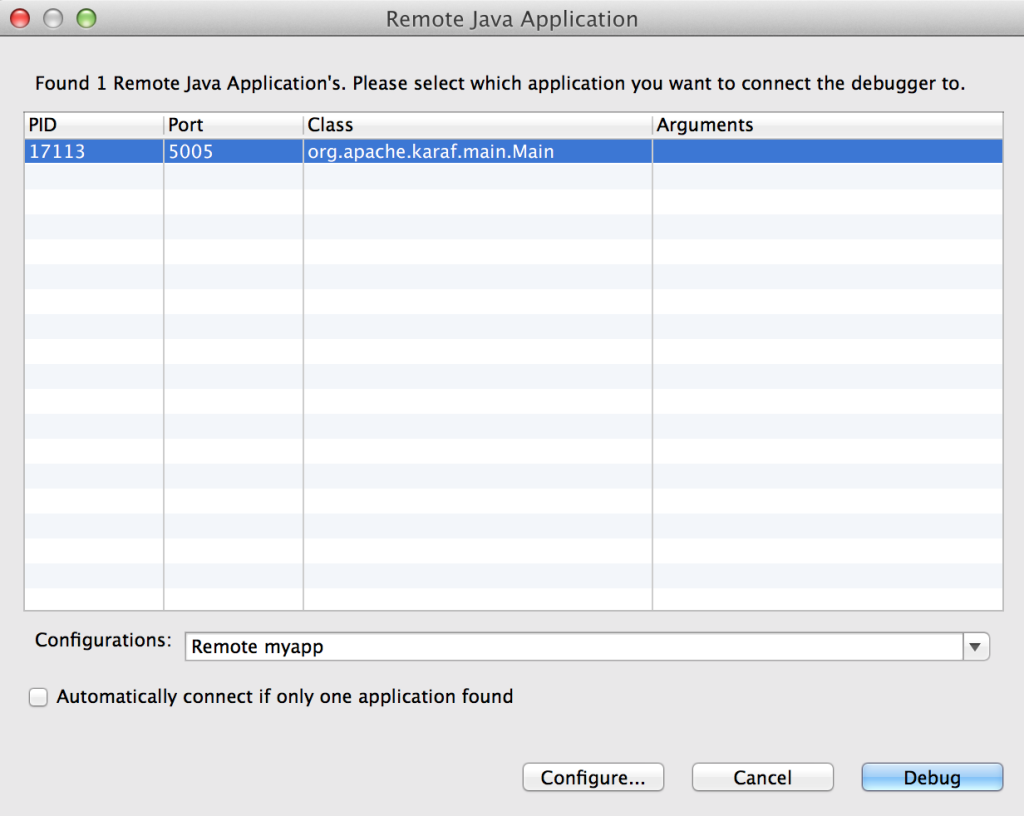
You may choose to customize the debug configurations by selecting the configure button, otherwise select Debug which will connect JDBS to Fuse. When the application running in Fuse hits one of the breakpoints previously set, the application will suspend at that point and JDBS will either prompt to switch into the debug perspective or switch automatically based on the configurations set in the JDBS workspace. With the application suspended, you are able to perform any debugging tasks you desire. A full overview on debugging in Eclipse is beyond the scope of this discussion and additional reference material can be found at the following links:
With only a few configuration steps, application can be tested and validated on a running remote Fuse instance. Remote application debugging is yet another method a developer has for creating reliable, robust applications.


Recent Comments